Writing Arduino programs in Wokwi
In this blog, I will write about writing basic Arduino programs in Wokwi Web-based Simulator.
Wokwi is an free online Electronics simulator. You can use it to simulate Arduino, ESP32, and many other popular boards, parts and sensors.
When working with Wokwi there is no need to worry about not having not enough component or breaking the board and Wokwi also make it easy to share your project.
So, it is a good place to start your arduino project.
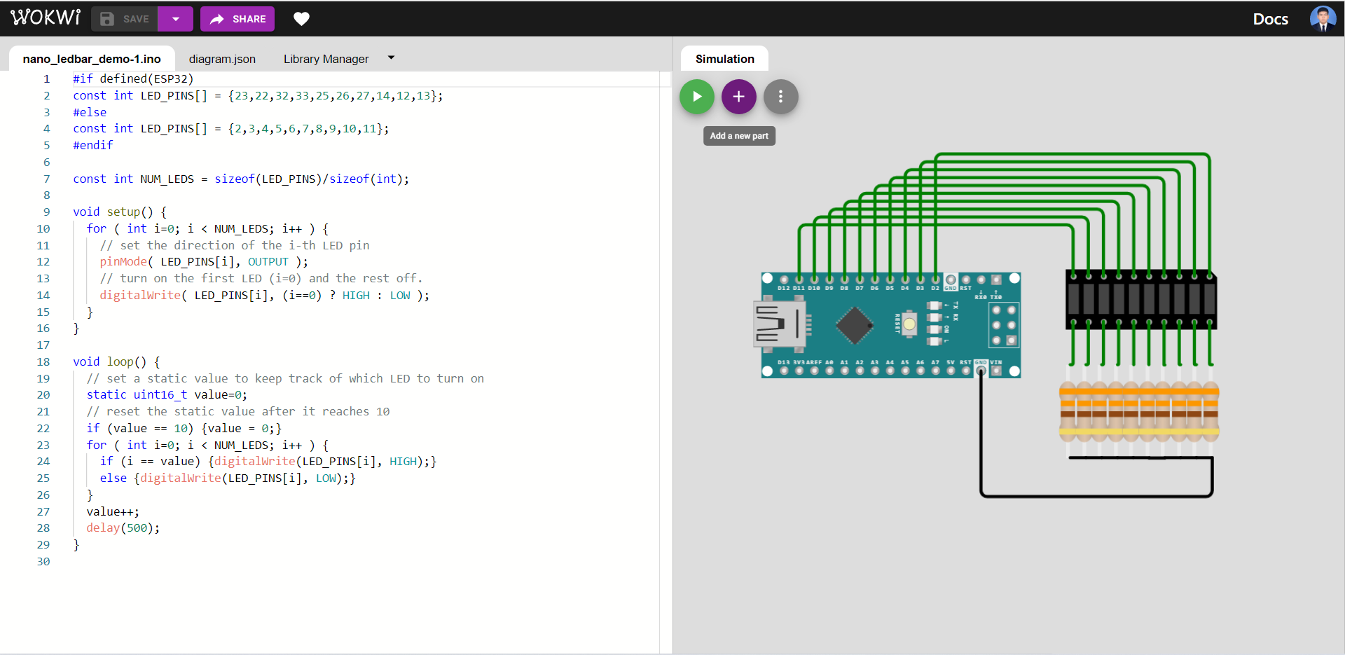
Adding components
Press the purple button with a plus sign to add a component to your circuit
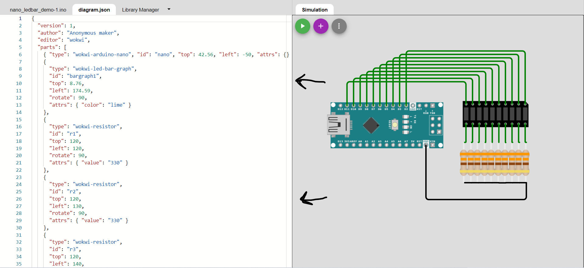
Configure components
Go to diagram.json and change property of your components here. You can also add components here.
Program you microcontroller
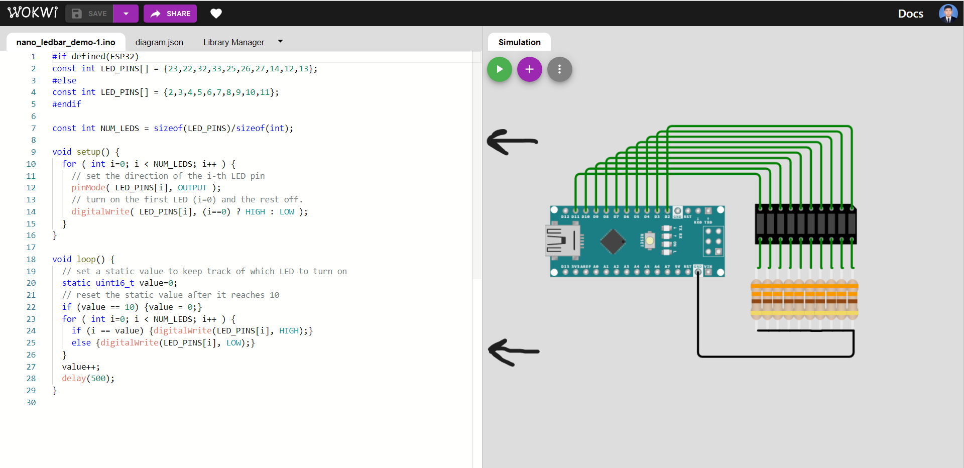
Write your code in the left side of your screen.
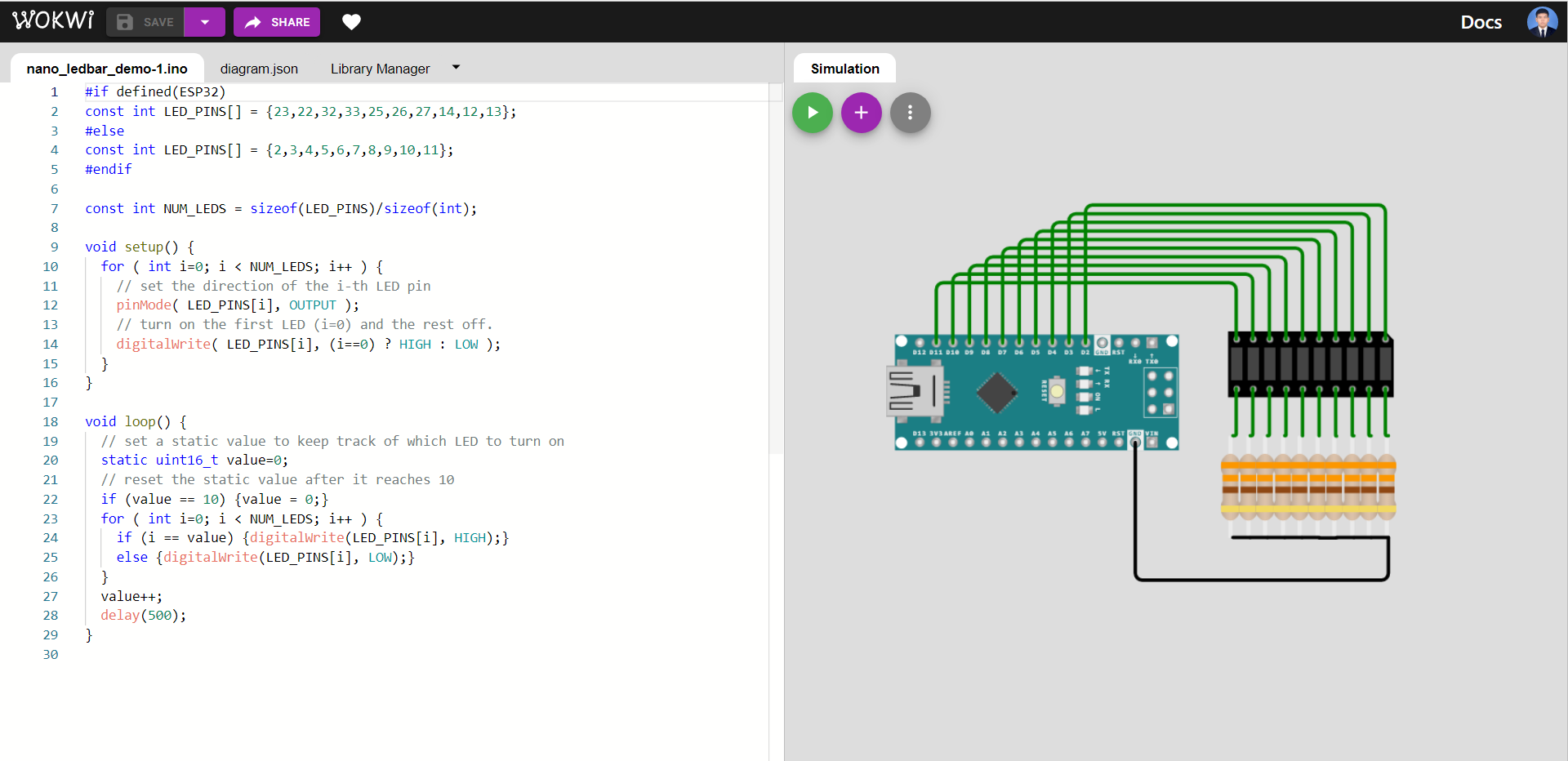
Starting simulation
Press the green button to start the simulation
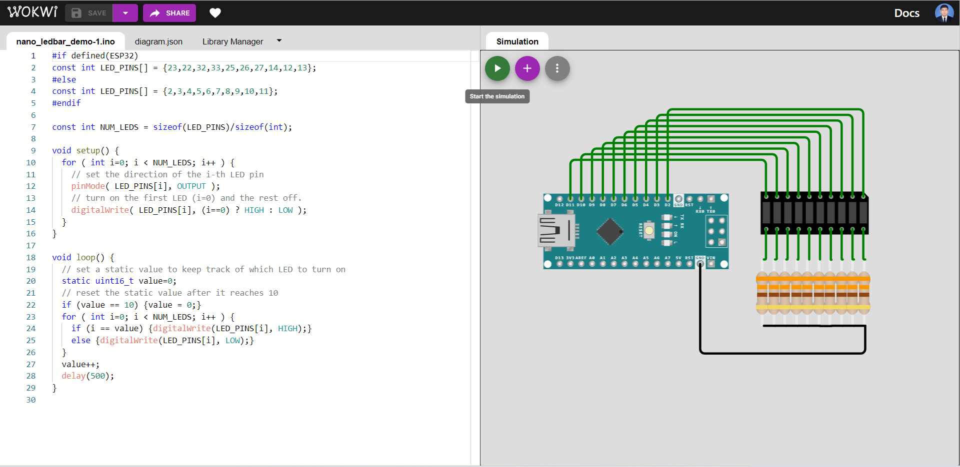
Program #1
LED changing pattern: A
Step 1. Initially, only one LED (at index=0) is ON, and the rest of the LEDs are OFF.
Step 2. The position of the ON LED should be moved to the next in a circular manner in a fixed time interval and then repeat Step 2.
#if defined(ESP32)
const int LED_PINS[] = {23,22,32,33,25,26,27,14,12,13};
#else
const int LED_PINS[] = {2,3,4,5,6,7,8,9,10,11};
#endif
Define pin numbers according to whether you are using ESP32 board or not. If you’re using ESP32 board then the first list will be used. otherwise the second list will be used.
const int NUM_LEDS = sizeof(LED_PINS)/sizeof(int);
Calculate the amount of pins we are going to use by dividing the size of pin numbers list in bytes by the size of an integer in bytes.
void setup() {
  for ( int i=0; i < NUM_LEDS; i++ ) {
    // set the direction of the i-th LED pin
    pinMode( LED_PINS[i], OUTPUT );
    // turn on the first LED (i=0) and the rest off.
    digitalWrite( LED_PINS[i], (i==0) ? HIGH : LOW );
  }
}
Set direction of LED pins according to the initial conditions.
void loop() {
  // set a static value to keep track of which LED to turn on
  static uint16_t value=0;
  // reset the static value after it reaches 10
  if (value == 10) {value = 0;}
  for ( int i=0; i < NUM_LEDS; i++ ) {
    if (i == value) {digitalWrite(LED_PINS[i], HIGH);}
    else {digitalWrite(LED_PINS[i], LOW);}
  }
  value++;
  delay(500);
}
Turn the next LED on and turn all other LED off. Wait 500 ms. Then repeat.
See the full code in action here.
Program #2
LED changing pattern: B
Step 1. Initially, all LEDs are OFF.
Step 2. Turn on the LEDs one by one with a time delay, starting at index=0 until all LEDs are ON.
Step 3. If all LEDs are ON, turn off LEDs one by one starting at index=n-1, where n is the total number of LEDs, until all LEDs are OFF, and repeat Steps 2-3.
#if defined(ESP32)
const int LED_PINS[] = {23,22,32,33,25,26,27,14,12,13};
#else
const int LED_PINS[] = {2,3,4,5,6,7,8,9,10,11};
#endif
Define pin numbers according to whether you are using ESP32 board or not. If you’re using ESP32 board then the first list will be used. otherwise the second list will be used.
const int NUM_LEDS = sizeof(LED_PINS)/sizeof(int);
Calculate the amount of pins we are going to use by dividing the size of pin numbers list in bytes by the size of an integer in bytes.
void setup() {
  for ( int i=0; i < NUM_LEDS; i++ ) {
    // set the direction of the i-th LED pin
    pinMode( LED_PINS[i], OUTPUT );
    // turn on the first LED (i=0) and the rest off.
    digitalWrite( LED_PINS[i], (i==0) ? HIGH : LOW );
  }
}
Set direction of LED pins according to the initial conditions.
void loop() {
  // Turn on the LEDs one by one with a time delay, starting from index 0.
  for ( int i=0; i < NUM_LEDS; i++ ) {
    digitalWrite(LED_PINS[i], HIGH);
    delay(500);
  }
  // Turn off the LEDs one by one with a time delay, starting from the last index.
  for ( int i=NUM_LEDS-1; i >= 0; i-- ) {
    digitalWrite(LED_PINS[i], LOW);
    delay(500);
  }
}
Turn on the LEDs one by one with a time delay, starting from index 0. After all the LEDs are on, Turn off the LEDs one by one with a time delay, starting form the last index. Then repeat the process.
See the full code in action here.
Program #3
LED changing pattern: C
Step 1. Initially, all LEDs are OFF.
Step 2. Turn on the first LED by increasing the duty cycle of the PWM signal driving the LED, until the LED is fully ON.
Step 3. Repeat Step 2 with the next LED until all LEDs are fully ON.
Step 4. If all LEDs are ON, turn off LEDs one-by-one by decreasing the duty cycles of the PWM signals until all LEDs are OFF and repeat Steps 2-4.
const int LED_PINS[] = {5,18,19,21};
const int NUM_LEDS   = sizeof(LED_PINS)/sizeof(int);
Define pin numbers that we are going to use and calculate the amount of pins that we are going to use.
#define OFF (LOW)
#define ON (HIGH)
Since we are using active HIGH LEDs. We define HIGH as ON and define LOW as OFF.
void setup() {

}
Since we are not setting anything up before the main code, we are going to leave the void setup() blank.
const int PWM_RESOLUTION = 8;
const int PWM_FREQ = 1000;
const int DUTY_MAX = (1 << PWM_RESOLUTION);
PWM_RESOLUTION is the resolution of LEDC channel. / PWM_FREQ is the frequency of pwm of the analog signals sent by analog pins. / DUTY_MAX is the maximum duty cycle possible for the selected resolution.
void turn_on() {
  for ( int i=0; i < NUM_LEDS; i++ ) {
      // config LEDC channel i to have PWN_ RESOLUTION of PWM_RESOLUTION and a pwm of PWM_FREQ frequency.
      ledcSetup( i /*channel*/, PWM_FREQ, PWM_RESOLUTION );
      // connect pin to the corresponding LEDC channel.
      ledcAttachPin( LED_PINS[i] /*pin*/, i /*channel*/ );
      // reduce duty cycle by 1 every 5 ms until it reaches 0.
      for ( int x=0; x < DUTY_MAX; x++ ) {
         ledcWrite( i, x );
         delay(5);
      }
      // unconnect pin from the LEDC channel and turn the LED on.
      ledcDetachPin( LED_PINS[i] );
      digitalWrite( LED_PINS[i], ON );
      delay(200);
  }
}
This is the function used to turn on the first LED by increasing the duty cycle of the PWM signal driving the LED, until the LED is fully ON.
void turn_off() {
  for ( int i=0; i < NUM_LEDS; i++ ) {
      // config LEDC channel i to have PWN_ RESOLUTION of PWM_RESOLUTION and a pwm of PWM_FREQ frequency.
      ledcSetup( i /*channel*/, PWM_FREQ, PWM_RESOLUTION );
      // connect pin to the corresponding LEDC channel.
      ledcAttachPin( LED_PINS[i] /*pin*/, i /*channel*/ );
      // reduce duty cycle by 1 every 5 ms until it reaches 0.
      for ( int x=0; x < DUTY_MAX; x++ ) {
         ledcWrite( i, DUTY_MAX-1-x );
         delay(5);
      }
      // unconnect pin from the LEDC channel and turn the LED off.
      ledcDetachPin( LED_PINS[i] );
      digitalWrite( LED_PINS[i], OFF );
      delay(200);
  }
}
This is the function used to turn off LEDs one-by-one by decreasing the duty cycles of the PWM signals until all LEDs are OFF.
void loop() {
  turn_on();
  turn_off();
}
Run the turn_on function and the turn_off function. Then repeat.
See the full code in action here
Program #4
LED changing pattern: D
Step 1. Initially, all LEDs are OFF.
Step 2. Turn on the first 4 LEDs using PWM signals, each with different duty cycles (e.g. 100%, 50%, 25%, 10%), and the rest of the LEDs are OFF.
Step 3. Move the positions of ON LEDs to the left by one position in a circular manner and repeat Step 3.
const int LED_PINS[] = {32,33,25,26,27,14,12,13};
const int NUM_LEDS   = sizeof(LED_PINS)/sizeof(int);
Define pin numbers that we are going to use and calculate the amount of pins that we are going to use.
#define OFF (LOW)
#define ON (HIGH)
Since we are using active HIGH LEDs. We define HIGH as ON and define LOW as OFF.
const int PWM_RESOLUTION = 8;
const int PWM_FREQ = 1000;
const int DUTY_MAX = (1 << PWM_RESOLUTION);
PWM_RESOLUTION is the resolution of LEDC channel. / PWM_FREQ is the frequency of pwm of the analog signals sent by analog pins. / DUTY_MAX is the maximum duty cycle possible for the selected resolution.
void setup() {
  for (int i=0; i < NUM_LEDS; i++) {
    // config LEDC channel i to have PWN_ RESOLUTION of PWM_RESOLUTION and a pwm of PWM_FREQ frequency.
    ledcSetup( i /*channel*/, PWM_FREQ, PWM_RESOLUTION );
    // connect pin to the corresponding LEDC channel.
    ledcAttachPin( LED_PINS[i] /*pin*/, i /*channel*/ );
  }
}
Configure LEDC channels and connect analog pins to the corresponding LEDC channel.
void loop() {
  // create static values to track which LEDs should be driven with .
  static uint16_t value_1=0;
  static uint16_t value_2=1;
  static uint16_t value_3=2;
  static uint16_t value_4=3;
  // Drive the corresponding LEDs pin with the corresponding duty cycle.
  for ( int i=0; i < NUM_LEDS; i++ ) {
    if (i == value_1){
      ledcWrite(i, (DUTY_MAX-1)*10/100);
    }else if (i == value_2) {
      ledcWrite(i, (DUTY_MAX-1)*25/100);
    }else if (i == value_3) {
      ledcWrite(i, (DUTY_MAX-1)*50/100);
    }else if (i == value_4) {
      ledcWrite(i, DUTY_MAX-1);
    }else {ledcWrite(i, 0);}
  }
  // increase the value of static values and reset their values once they reached 10
  value_1 = (value_1+1) % NUM_LEDS;
  value_2 = (value_2+1) % NUM_LEDS;
  value_3 = (value_3+1) % NUM_LEDS;
  value_4 = (value_4+1) % NUM_LEDS;
  delay(500);
}
Turn on the first 4 LEDs using PWM signals, each with different duty cycles (e.g. 100%, 50%, 25%, 10%), and the rest of the LEDs are OFF. Move the positions of ON LEDs to the left by one position in a circular manner and repeat.
See the full code in action here
Creating Header files and Cpp files for easier OOP programming
Sometime, We want to use OOP for reusability, modularity, readability, etc. One way we can do this is to create classes in the main sketch, but it’s not ideal for programs with high code length. The other way to do OOP programming in arduino is to separate the classes into different files. This method make it easier to add new functionality or fix bugs in longer code.
For the next two programs we are going to create an OOP version of Program #1 and Program #2 using Pin class to control pins
Pin.h (The header file)
This is the class declaration for when your programs use the Pin class. Including the arduino header file is neccessary because we are going to use basic arduino functions in out Pin class.
#ifndef PIN_H
#define PIN_H

#include <Arduino.h>

// This is a C++ class for an Arduino digital pin
class Pin {
   public:
     enum class Direction { OUT=0, IN=1, IN_PULLUP=2 };

     // a class constructor with parameters
     Pin( int8_t pin, Direction dir=Direction::IN, bool init_value=false );

     // read the input pin
     bool read( bool force_update=true );

     // write the output pin
     void write( bool value, bool force_update=true );

     // toggle the output pin
     void toggle( bool force_update=true ) ;

     // assign a new value to the output pin
     void operator=(bool value);

     // set the direction of the pin
     void setDirection( Direction dir, bool init_value=false );

     // inline methods
     inline operator bool()           { return _value; }
     inline int8_t getPin()           { return _pin;   }
     inline bool   getValue()         { return _value; }
     inline Direction getDirection()  { return _dir;   }

     // the class destructor
     ~Pin() {}

   protected:
     // initialize the GPIO pin
     void init( int8_t pin, Direction dir, bool init_value );
     // update the logic state of the GPIO pin
     void update();

   private:
     int8_t     _pin;   // the GPIO pin number
     bool       _value; // the value of pin
     Direction  _dir;   // the direction of pin
};

#endif
Pin.cpp (The Cpp file)
This is where you add functionality to your Pin class.
#include "Pin.h"

// Class implementation for Pin.h

Pin::Pin( int8_t pin, Direction dir, bool init_value ) {
  init( pin, dir, init_value );
}

bool Pin::read( bool force_update ) {
  if (force_update) { update(); }
  return _value;
}

void Pin::write( bool value, bool force_update ) {
  _value = value;
  if (force_update) { update(); }
}

void Pin::toggle( bool force_update ) {
  if ( _dir == Direction::OUT ) {
     _value = !_value;
  }
  if (force_update) {
     update();
  }
}

void Pin::operator=(bool value) {
  write( value );
}

void Pin::setDirection( Direction dir, bool init_value ) {
  init( _pin, dir, init_value );
}

void Pin::init( int8_t pin, Direction dir, bool init_value ) {
  _pin   = pin;
  _dir   = dir;
  _value = init_value;
  if ( _dir == Direction::OUT ) {
    pinMode( _pin, OUTPUT );
  }
  else if ( _dir == Direction::IN ) {
    pinMode( _pin, INPUT );
  }
  else if ( _dir == Direction::IN_PULLUP ) {
    pinMode( _pin, INPUT_PULLUP );
  }
  update();
}

void Pin::update() {
  if ( _dir == Direction::OUT ) {
    digitalWrite( _pin, _value ? true : false ) ;
    //Serial.printf( "Debug> write output: %d on pin %d\n", _value, _pin );
  }
  else {
    _value = digitalRead( _pin ) ? true : false;
    //Serial.printf( "Debug> read input: %d on pin %d\n", _value, _pin );
  }
}
Program #5
LED changing pattern: A
Step 1. Initially, only one LED (at index=0) is ON, and the rest of the LEDs are OFF.
Step 2. The position of the ON LED should be moved to the next in a circular manner in a fixed time interval and then repeat Step 2.
#include "Pin.h"
Include the Pin.h Header file.
const int LED_PINS[] = {23,22,32,33,25,26,27,14,12,13};
const int NUM_LEDS = sizeof(LED_PINS) / sizeof(int);
Define pin numbers that we are going to use and calculate the amount of pins that we are going to use.
void setup(){

}
Since we are not setting anything up before the main function, we can leave the setup() blank.
void loop(){
   // set a static value to keep track of which LED to turn on
   static int value=0;
   // reset the value after it reaches 10.
   if (value == 10) {value = 0;}
   // turn the LED corresponding to the static value on. Turn all other LEDs off.
   for (int i = 0; i < NUM_LEDS; i++){
      // create a PIN class object with OUT direction and set its value according to which LEDs should be turned on.
      Pin pin(LED_PINS[i], Pin::Direction::OUT, (i == value) ? HIGH : LOW);
   }
   value++;
   delay(500);
}
Turn the first LED on and turn all other LED off. Wait 500 ms. Then turn the next LED on and turn all other LEDs off. Repeat this step for all LED. Once the last LED has been turned on, Do the entire main function again starting form the first LED.
See the full code in action here
Program #6
LED changing pattern: B
Step 1. Initially, all LEDs are OFF.
Step 2. Turn on the LEDs one by one with a time delay, starting at index=0 until all LEDs are ON.
Step 3. If all LEDs are ON, turn off LEDs one by one starting at index=n-1, where n is the total number of LEDs, until all LEDs are OFF, and repeat Steps 2-3.
#include "Pin.h"
Include the Pin.h Header file.
const int LED_PINS[] = {23,22,32,33,25,26,27,14,12,13};
const int NUM_LEDS = sizeof(LED_PINS) / sizeof(int);
Define pin numbers that we are going to use and calculate the amount of pins that we are going to use.
void setup(){

}
Since we are not setting anything up before the main function, we can leave setup() blank.
void loop(){
   // Setting the LED pins outputs' to HIGH one by one.
   for (int i = 0; i < NUM_LEDS; i++){
      Pin pin(LED_PINS[i], Pin::Direction::OUT, HIGH);
      delay(500);
   }
   // Setting the LED pins outputs' to LOW one by one.
   for (int i = NUM_LEDS-1; i >= 0; i--){
      Pin pin(LED_PINS[i], Pin::Direction::OUT, LOW);
      delay(500);
   }
}
Turn on the LEDs one by one with a time delay, starting from index 0. After all the LEDs are on, Turn off the LEDs one by one with a time delay, starting form the last index. Then repeat the process.